
Inhaltsverzeichnis
E-601 (E41)
Allwellenempfänger Uster (All Wave Receiver 41), E41; developed and produced by Zellweger AG, Uster.
The Swiss company Zellweger, Uster, has constructed a shortwave receiver using battery tubes to fit their "Fahrbar Leichte Funkstation 40", the famous FL wireless station. This „FL Empfaenger“ or „Empfaenger Uster“ is based on National's famous PW-4 tuning capacitor, similar as the Autophon E39, and uses plug in coil sets and battery valves.
The receiver covers a very large part of the spectrum from 100 kHz up to 60 MHz, it uses plug-in coil sets to change wavebands. The frequency marks are quite coarse.

Technical Data
- Frequency range: 100 kHz - 60 MHz in ten frequency ranges, Plug in coil sets to select frequency range, on the coil sets, a coarse frequency dial is available.
- Sensitivity: AM (A3) / Selectivity: „breit“ (wide) ± 3.5 kHz, „mittel“ (medium) ± 2 kHz, „schmal“ (narrow) 100 kHz.
Power Supply
- Mains: Mains power supply operated from 110, 125, 145, 220, 250 Volts, delivering 6 V (0,47 A, for valve heaters) and 120 V (35 mA, plate voltage).
- Accumulator / Batteries: 6 V, the plate voltage of 120 V is generated in the mains power supply.
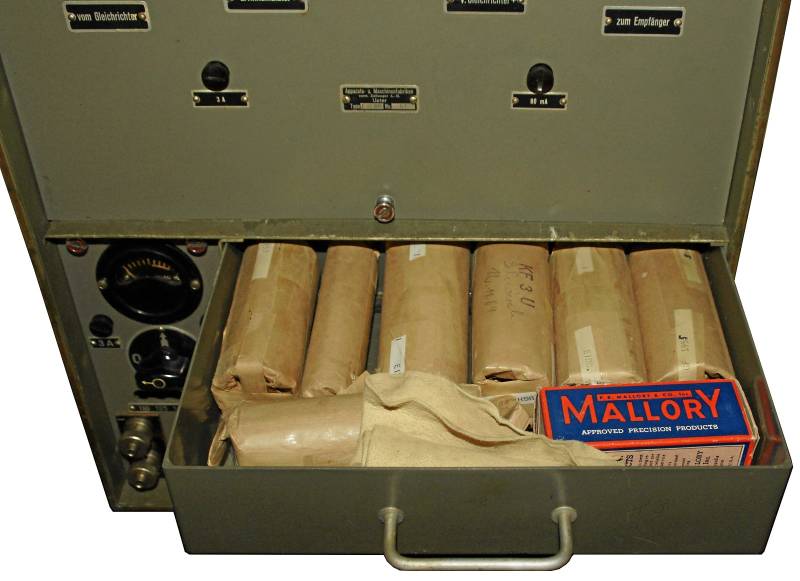
The receiver can be powered from 6V accumulators or from mains. The 6V DC voltage is used directly for valve heaters and via a „Mallory vibrator“ to generate the B+ voltage of 120V which will be rectified again.
The mains power supply accepts different voltages from 110 - 250 V and delivers an output voltage of 6V DC. This will be used to heat the valves and to feed the „Mallory vibrator“ to generate the B+, exactly in the same way as if the receiver is fed from 6V accumulators.
Only in an emergency, the receiver can be powered with plate voltage from two 60V B+ batteries.
Dimensions
- Receiver Case E41: 410 x 225 x 350 mm, 17 kg
- Coil sets case E41: 410 x 225 x 350 mm, 17 kg
- Mains power supply E41 WR: 425 x 470 x 260 mm, 20 kg
- two NiFe - Accumulators, 17,8 kg each
Accessories
- The Standard antenna is a 1,8 m Whip antenna (consisting of six elements, which are stored in the lid of the coil sets case) or a long wire antenna. As an alternative, for direction finding purposes in the 100 - 1500 kHZ ranges, the direction finding antenna of the receiver E31 can be used.
- Headphones, when plugged in in the left pair of headphones sockets, a noise limiter consisting of two diodes is activated.

Operation
When the set was introduced, many wireless operators turned out to be discontented: To simplify operation, Zellweger had merged some functions together in one control; an experienced operator could get out much more out of a partly disturbed signal by tweaking the separate A.F. and R.F. gain and the crystal filter of the E39.
The receiver system consists of the 41 x 22,5 x 35 cm receiver case (17 kg), a plug-in coils case with the same dimensions with a compartment to store headphones and antenna cables. The mains power supply is twice as high with it's 42,5 x 47 x 26 kg and has a weight of 20 kg, two Fe-Ni accumulators with 17,8 kg each are also needed.
The receiver can be fed from a 1,8 m whip antenna, a long wire antenna or for direction finding purposes from the directional antenna ob the much older receiver E31.
The operation scheme of the Zellweger E41 is very simple, as the engineers at Zellweger did couple certain functions to simplify the operation of the receiver and to keep the number of controls down.
Connect the whip antenna with the antenna socket, the mains power supply with the power supply socket and test the heaters voltage indicated on the instrument of the power supply.
Plug in the coil set with the corresponding band range containing the desired frequency. The main switch is combined with the volume control, turn it to the right side for normal (AM) reception and to the left for reception of morse code (CW) transmissions. Tune to the desired frequeny, there are some quite coarse markings in on the coil sets which allow tuning to the nearest 20 kHz. Use the fine tuning („Feineinstellung“) for optimum readibility or to adjust the beat note of the BFO. The control automatic gain control (”Aut. Lautstärkeregulierung”) activates the AGC. In AM mode, it is always active, for CW reception, You might try manual gain control. In case of adjacent channel interference, You might switch from the „wide“ to the „medium“ I.F. bandwidth, the narrow („schmal“) position can only be used for CW reception, an 900 Hz audio filter is switched automatically. The asymmetric I.F. quartz filter is tuned to lower sideband reception and tends to „ringing“ effects. The output power of the E41 is sufficient for headphones use only, the signal of the left pair of headphone jacks is fed through two antiparallel diodes acting as noise limiter. The right pair of jacks marked with red colour has a slightly higher output power.
Technical Principle
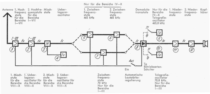
The Zellweger E41 operates as a single conversion receiver with an intermediate frequency of 70 kHz in bands 1 - 3: after two R.F. amplifier stages, the signal is mixed to the first I.F. of 70 kHz and fed to the demodulator after another amplifier stage. The BFO is acting on 70,8 kHz which will result in a 800 Hz beat note in CW mode.
In the bands 4 - 7, the receiver acts as a single conversion set, too: after the first two R.F. amplifier stages, the signal is mixed to an intermediate frequency of 465 kHz. The signal is fed to the demodulator after two I.F. amplifier stages, the BFO oscillator's frequency is 465,8 kHz to achieve a BFO note of 800 Hz.
In the bands 8 - 10, the receiver's circuitry acts different: the first R.F.amplifier stage acts as first mixer, the second as first oscillator to generate a first intermediate frequency variable from 3 - 6,35 MHz. In the second mixer, this I.F. is mixed to the second I.F. of 465 kHz, the E41 acts as a double conversion receiver. After two I.F. amplifier stages, the signal is demodulated; for CW reception, the BFO signal of 465,8 kHz is fed to obtain a 800 Hz beat note.
Valve setup
The valves used in this receiver are the battery valve KF3U, as first and second mixer and in the first audio stage, a KH1M is used; and as final audio tube a double triode CB220M is used.
Development
The receiver E41 has been developed by Zellweger, Uster, during the years of World War II, they used the kind of battery tubes (made by Tungsram in Budapest), which were for Switzerland still available in those days.
Field use
The Swiss Army bought 138 standalone units of this receiver, another 198 sets made part of complete wireless stations, like the FL40 (Fahrbar Leicht 40), TS40 (Tragbar Schwer 40); in the KL43 (Kurz Lang 43) and the M44 (Motorisierte Funkstation 44), the same receiver has been used with a reduced number of plug in coil sets. Eventually, the E41 replaced the Lorenz E509/I as main receiver of the G1,5K (“Grossen 1,5 kW Kurzwellenstation”) and has been in use as main receiver in the G3L and G1,2K wireless stations of the airforce.


