
Inhaltsverzeichnis
E-645: Shortwave Receiver Siemens E311
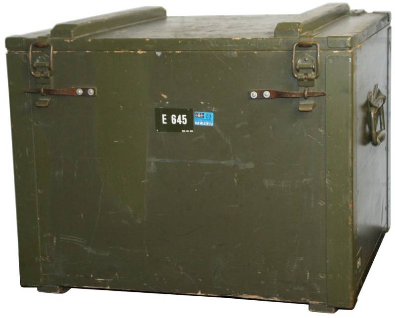
E-645, Shortwave Receiver Siemens E311; manufactured by Siemens Elektrogeraete GmbH, Munich.
The Siemens E-311 appeared in early 1960's in parallel to the E-310 and was advertised as an alternative to communications receivers from Collins or Rohde & Schwarz. It has not only been in use in Germany but has also been used by the Swiss Army, where it carried the designation E-645.
From the different variants of the E-311, which can be differentiated among other things by the number of the thermostate lamps, the variant Rel 445 E311e1 was certainly used by the army in the monitoring service and as main receiver in the SE-302 high power shortwave station.

Technical Data
- Frequency range: 1.5 MHz - 30.1 MHz
- Analog dial, linear analog dial, accuracy better then 100 Hz.
Power Supply
- Mains: 110 - 220 V
Dimensions
- 475 x 295 x 390 cm, 25 kg
Accessories

Operation
 With it's grey steel cabinet with the dimensions 47,5 x 29,5 x 39 cm and a weight of only 25 kg, the Siemens E-311 is a quite compact and lightweight commercial communications receiver. All connectors can be found on the front panel, even the mains cable for the 110 - 220 V mains supply. The 16 valves in the receiver have a power consumption of 70 W, the quartz ofen needs another 30 Watts.
According to the setting of the band switch, another segment of the frequency dial is visible in the dial window, on the dial, you find the coarse 100 kHz marks. A mechanical digital (odometer type) display will indicate the frequency with a resolution of 1 kHz, there are incremental lines for 100 Hz. With the coarse tuning knob at the left hand below the frequency dial, you select the next lower 100 kHz frequency mark on the band dial, a indicator lamp just above the dial will inform you that the receiver is locked on the the correct 100 kHz position, then use the fine tuning knob at the right lower hand to tune to the 10 kHz and 1 kHz digits of the desired frequency.
The speaker grille of the internal monitor speaker is found in the left upper corner of the frontpanel, the speaker is activated when the volume control is pulled out. At the right, you find the switch for the noise limiter, the 100 kHz lock indicator and below the indicators for the quartz ofen and oscillator temperature. Below, you find the bandwidth control, and further below the rotary volume control and the modes switch for AM(A3), CW(A1), SSB(A3a) and „Calibrate“ just next to it.
On the right side of the front panel - from top - the signal strength meter and the meter switch are located, the meter can be set to indicate the audio level. Next to the fine tuning knob, you find the band selector and below the RF gain control and the antenna tuner control.
In the bottom row of switches, you find the mains switch, two fuses, the SYNC switch which activates the 100 kHz interpolation oscillator, the AGC switch with two decay speeds, the squelch and the sideband selector. In the right lower corner, there is a row of 6,3 mm sockets for LINE out, speaker and headphones and for the optional longwave / VLF adaptor.
In practical use first select the desired band segment, to tune the set to 6155 kHz, this will be the 3,4 - 7,5 MHz range. Use the Coarse / Main tuning knob to tune to 6,1 MHz, You hear the relay clicking and the 100 kHz lock indicator will be lit. Use the tine tuning control to tune the „interpolator“ VFO to 55, now You should be able to hear the signal on 6155 kHz coming to You from Vienna. Use the preselector RF TUNING to tune to signal maximum.
The small range of the fine tuning oscillator makes tuning through a complete shortwaveband a bit cumbersome - when You cross the 6099 - 6101 kHz point, You have to set the main tuning knob to the next 100 kHz segment and turn down the fine tuning knob of the interpolator from 99 to 01. For these situations, You can switch off the 100 kHz locking circuitry and use only the coarse tuning knob to search for a certain signal. When using the 100 kHz lock switched on and the set carefully tuned, the frequency dial accuracy is better then 1 kHz - a good result for a set designed in the sixties. The nonstandard signal strength meter calibration and the non very straightforward layut of the frontpanel controls are the backdraws of this receiver, reception quality is very good and the set's stability is excellent thanks to heated quartz and oscillators.
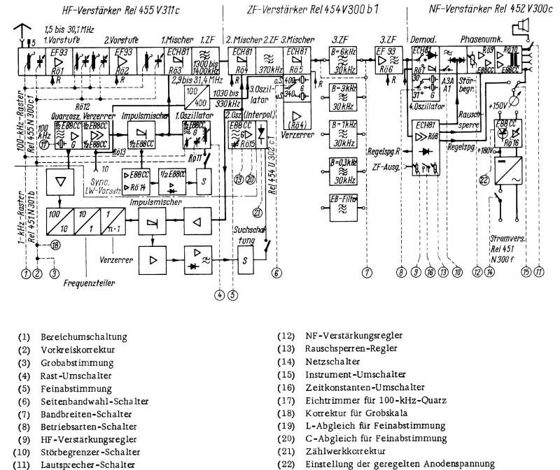
Technical Principle

The RF signal coming from the antenna jack first has to pass the preselector stage, an amplifier (V1, V2) and filter stage and will be coverted to the first intermediate frequency of 1,3 - 1,4 MHz in the first mixer (V3).
The oscillator frequency of 2,9 - 31,4 to generate the first I.F. can be tuned continuosly or the oscillator can be set to lock every 100 kHz by help of a magnetic variometer controlled by the harmonics of a 100 kHz crystal, You can hear the relay's click noise when the receiver is locking on to a 100 kHz channel. A second tuneable oscillator called the „interpolation oscillator“ is used to tune the 0 - 99 kHz digits of the desired reception frequency.
In the second mixer (V4), an I.F. of 370 kHz is generated and mixed with an oscillator signal of 400 resp. 340 kHz in the third mixer (V5) to end with the third intermediate frequency of 30 kHz. After having passed a 30 - 33,5 kHz band filter, the IF signal is amplified (V6) and demodulated for single sideband reception or will have to pass a detector diode in AM mode. A beat frequency oscillator of 31 MHz is used for CW reception.
The audio signal then is passed to the AF preamplifier (V9) and output stage (V10).
Valve setup
V1, V2 (EF93, two RF preamplifier stages); V3 (ECH81, 1st mixer stage, IF 1.3-1.4 MHz); V4 (ECH81, 2nd mixer stage, 370 kHz); V5 (ECH81, 3rd mixer stage, 30 KHz); V6 (EF93, 1st IF amplifier); V7 (ECH81, oscillator SSB reception); V8 (ECH81, AGC amplifier); V9 (E88CC, audio preamplifier); V10 (E88CC, AF final amplifier); V11 (E88CC, 1st oscillator); V12a (E88CC, oscillator 100 kHz); V13 (E88CC, impulse mixer / oscillator lock); (V14 (E88CC, longwaves oscillator lock)); V15 (E88CC, interpolation oscillator);
Mains rectifier, V16 (E88CC, voltage regulation anode voltage).