
Inhaltsverzeichnis
E-625: National HRO-7T
E-625, National HRO-7T; developed and produced by the National Company Inc., Malden, MA.
In several lists, you can find informations about receivers that have been acquired in small numbers and got assigned an E-6xx designation of the Swiss Army. One of these sets it the HRO-7T, a successor of the National HRO, of which also a few sets have been bought.
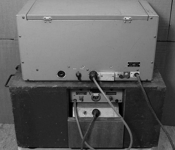
Telefunken Zürich provided a wooden housing with an integrated speaker, which also had space to store the typical HRO „doghouse“ power supply and the coil sets.
Technical Data
- Frequency range: 0.05 - 30 MHz (standard 4 coil sets 1.7 - 4 / 3.4 - 7.2 / 7 - 14 / 13 - 30 MHz, optional coil sets 900 - 2050 kHz, 480 - 960 kHz, 180 - 430 kHz, 100 - 200 kHz and 50 - 100 kHz).
- Analog dial, micrometer dial with calibration curves.
Power Supply
- Mains with „Doghouse Power Supply“ PSU 697: 115, 230 V
- Accumulator / Batteries: with optional vibrator power supply for 6 V (686B)
Dimensions
- 495 x 280 x 260 mm, 29.5 kg
Accessories
- Headphones
A vibrator power supply 686S could be used to power the receiver from a 6V DC source. Also the crystal calibrator and the FM product detector were not standard accessories but could be ordered separately and could be plugged in to an accessory socket on the rear of the set.
The HRO-7T has no internal speaker, it needs a high impedance speaker, e.g. National's MCR or the rack speaker RFSH with an integrated audio transformer. According to the manual, the final tube can be pulled out for power saving reasons if the receiver is only used with headphones.
Operation
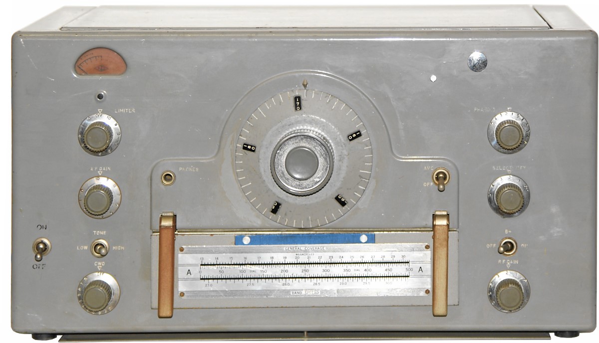
The HRO-7 T is a single conversion superhet using plug in coil sets for changing bands like found in the classic HRO. On the coil sets, there is a printed conversion table for micrometer dial reading and frequency, similar but easier to read then the logging charts on the original HRO dials. You find two frequency reference charts for general coverage use and for bandspread in the amateur bands.
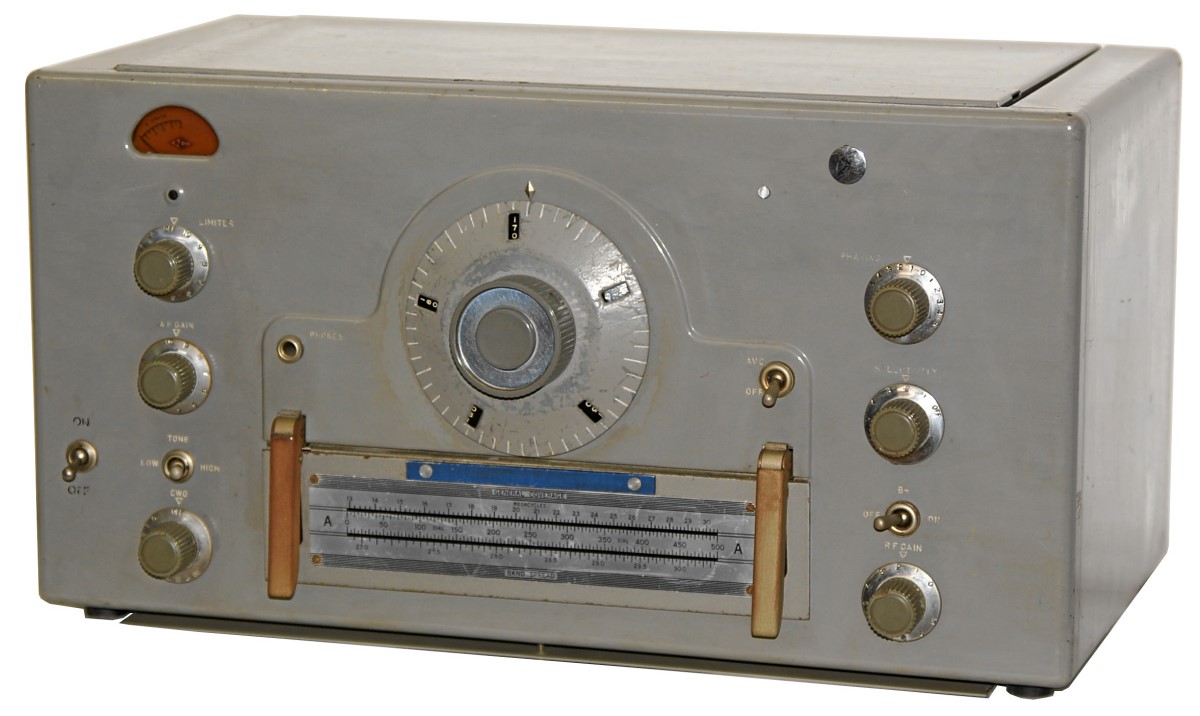
The main tuning knob with the „micrometer“ dial, on which the numbers of the logging dial can be read, is found in the middle of the front panel. On the coil set just below the tuning knob, there is a frequency conversion chart to determine the frequency of a signal from the reading of the micrometer dial.
At the left, you find the signal strength meter. The next control is the noise limiter followed by the AF gain control, the volume control. The switch underneath is the tone control to cut off high frequency parts of the audio spectrum, the bottom control activates the BFO for the reception of telegraphy signals.
In the right column of controls, the top button acts als rejection control like a phasing filter, the rotary control below lets you regulate the passband width of the crystal filter. The next switch will turn on B+, the plate voltage: let the B+ switched off when the receiver is in standby, and B+ must be turned off when changing coil sets!
The bottom control at the right is the RF gain control.
 Most coils sets come with double frequency charts, one for general coverage use and the second one for bandspread use in the amateur bands. The setting general coverage or bandspread tuning is changed by machine screws in certain positions on the coil sets.
Technical Principle
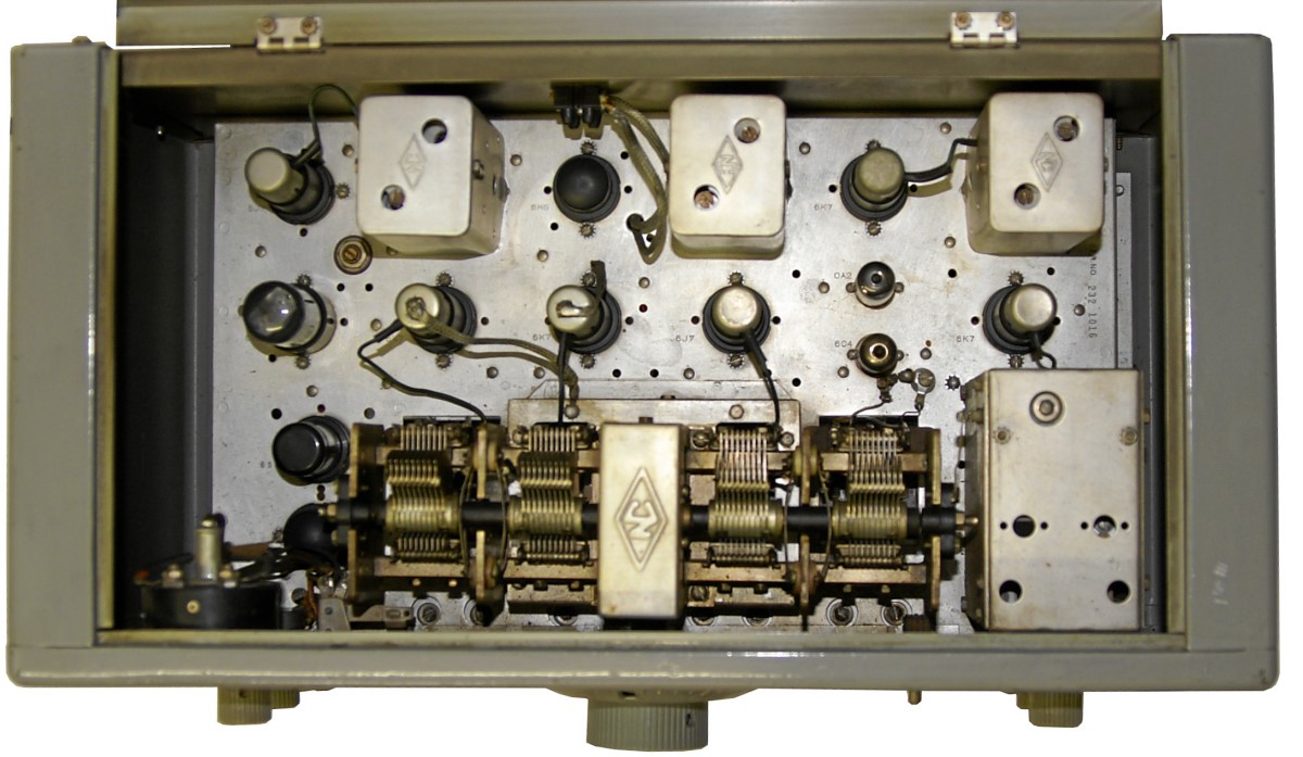
Technically, the HRO-7 is a single conversion superheterodyne with two RF preamplifier stages. The signal coming from the antenna will pass a first tuned circuit of the RF preamplifier (V1: 6K7) and a second tuned circuit of the RF amplifier stage (V2: 6K7). When mixed with the oscillator (V7: 6C4) signal in the mixer stage (V3: 6J7), the intermediate frequency of 456 kHz is generated.
The intermediate frequency will pass the crystal or Lamb filter where the bandwidth can be regulated and unwanted interfering signals can be rejected using the rejection tuning feature. After two IF amplifier stages (V4/V5: both 6K7), the signal is demodulated in the detector stage (V6: 6H6), the AF preamplifier stage (V11: 6SJ7) is followed by the AF final stage (V12: 6V6GT). For reception of CW morse codes transmissions, the signal of the beat frequency oscillator BFO (V9: 6J7) is injected before detection, a 6H6 (V10) acts in the noise limiter.
The external power supply 697, in which you find an 80 rectifier tube for the B+ / plate voltage of 240 V, and which will also deliver the 6,3 V heaters voltage comes in a strange shaped metal cabinet - everyone who has ever seen a „doghouse“ power supply will know what I'm talking about.
Valve setup
V1 (6K7, 1st RF preamplifier); V2 (6K7, 2nd RF preamplifier); V3 (6J7, mixing stage); V7 (6C4, oscillator); V4 (6K7, 1st IF stage); V5 (6K7, 2nd IF stage); V6 (6H6, demodulator, AVC amplifier); V9 (6J7, BFO); V10 (6H6, noise limiter); V11 (6SJ7, AF preamplifier); V12 (6V6GT, AF power amplifier).
In the power supply 697: Gl (5Y3GT, power rectifier), V8 stabilizer 0A2.
Development
Field use
For the Swiss Army, Telefunken Zurich made a special wooden rack with space for the the integrated power supply, a switchbox for receiver operation with or without speaker, and a storage rack for the frequency band coils.
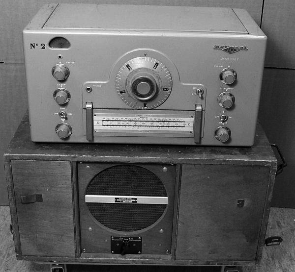

This wooden rack is still missing in my collection, so if you have one for sale, let me know.