
EF50

|
Variants
|
|||||||||||||||||||||||||||||||||||||||||||||||||||


|
Hits: 9427 Replies: 6
EF50 suppressor action
|
|
|
Joe Sousa
06.Nov.10 |
1
Fellow radiophiles, The high transconductance EF50 RF pentode with gm=6.5mS was primarily designed in 1938 to have the suppressor grid G3 biased at cathode potential. However, G3 exhibits a usable control (transconductance, gm3) on plate and screen currents. Jacob Roschy brought this pentode to my attention. Thank you Jacob. One noteworthy characteristic of the G3 action is that despite it's ability to control plate and screen currents, it did not lower the internal plate resistance greatly when G3 is grounded, as is usually found with dual control pentodes, such as the 6AS6. The high plate resistance is the inverse of the slope of the plate curves. It could be said that the EF50 has two built-in modes of operation for the Suppressor grid G3: When G3 is grounded, it has little effect (small gm3) on the plate and screen currents, but after sufficient negative bias is applied, and at sufficiently low plate voltages or screen voltages, it can control the plate and screen currents. This means that the EF50 can be used in very different applications if the external bias voltages are modified accordingly. The following curve families illustrate this behaviour beyond what was published in it's extensive data sheets, in particular by Mullard, as scanned by Frank Philipse and available at the National Valve Museum. Plate curve families as a function of Control grid G1 voltage. Each plot has a different Screen grid G2 voltage.
Plate curve families as a function of Suppressor grid G3 voltage. Each plot has a different Screen grid G2 voltage.
Screen grid G2 curve families as a function of Suppressor grid G3 voltage. Each plot has a different Screen grid G2 voltage.
Triode curve families with Plate and Screen grid G2 swept together as a function of the Control grid G1 and Suppressor grid G3 voltage. Note in the second plot how insensitive the cathode current (IK=IP+IG2) is to Suppressor grid voltages. This sweep was narrowed to 50V for greatest sensitivity of Plate and Screen grid G2 currents to Suppressor grid voltage. While G3 affects the plate and screen currents individually very strongly as seen above, their sum, or cathode current, stays very constant.
Note that either a reduced Plate voltage or a reduced Screen voltage G2 enhance the action of the suppressor grid G3 on Plate and Screen currents. As with most other pentodes, G3 has little effect on the sum of plate and screen currents, which are the same as the cathode current. Refer to suppressor grid G3 measurements for curve traces on other pentodes. Regards, -Joe |
|
Jacob Roschy
12.Nov.10 |
2
The article below «Amplified Automatic Gain Control » was found in the October 1951 issue of the «Wireless World». This article fits pretty well to the examinations that Joe Sousa has shown in his post above. Its just a practically application about the EF50's dual control properties by using its suppressor grid g3 as second control grid.
Amplified Automatic Gain Control by using the EF50
The performance obtainable from the suggested circuit can be illustrated by the following measurements made on a t.r.f. receiver with a single controlled valve. As the input was increased from 100 µV to 0.3 volt, the output increased by less than 2 dB; in a typical 4-valve superhet with two controlled stages but non-amplified a.g.c. the output increases by approximately 15 dB for the same range of input signal amplitude. The circuit to be described embodies suppressor-grid injection of the control voltage. The application of a negative bias to the suppressor grid of a pentode produces markedly different effects from a negative potential applied to the control grid. The effect of varying the control-grid potential is to vary the total (i.e. anode + screen) current and the curve of total current plotted against control-grid potential is similar to that of a triode.
Fig. 1 Typical curves illustrating variation of screen and anode current with suppressor-grid potential. The effect of varying the suppressor-grid potential however is to vary the ratio in which the total current is divided between the screen and the anode. This is illustrated in Fig. 1, which shows that increase in negative suppressor bias decreases the anode current and increases the screen current, and, provided the screen-cathode potential is maintained constant the total current is substantially independent of suppressor-grid potential. By negatively biasing the suppressor grid the anode current is reduced but - more important in the circuit to be described - the change in anode current per volt change in grid potential is also reduced in the same ratio; in other words the mutual conductance of the pentode is reduced by application of negative bias to the suppressor grid. Thus the application of negative bias to the suppressor grid of a pentode has an effect similar to that of applying negative bias to the control grid of a variable-mu valve. There are, however, two significant differences to be noted; first, the mutual conductance of a pentode can be reduced to zero by a sufficiently large suppressor bias but the mutual conductance of a variable-mu valve can only be reduced to a low value by application of control-grid bias. In other words the anode-current / suppressor-potential curve has a sharper cut-off than the anode-current / control-grid potential curve for a variable-mu valve. However, no distortion occurs even if the valve is biased near suppressor cut-of, because the control grid is still modulating the full cathode current. Second, the cathode current of a variable-mu valve is reduced to a very low value by a large negative bias on the control grid, but the cathode current of a pentode is substantially unaffected by application of a large bias to the suppressor grid. This constancy of cathode current with variation of suppressor-grid bias plays an essential part in this a.g.c. circuit and is largely responsible for the simplicity of the circuit. The use of suppressor injection enables high-slope pentodes of the EF50 type to be used as automatic-gain-controlled r.f. or i.f. amplifiers. A disadvantage of suppressor-grid control for valves of the EF50 type is that the suppressor-grid base is usually longer than the control-grid base of a Variable-mu pentode, and a.g.c. voltages of the order of 50 volts are necessary for effective control. Thus d.c. amplification of the a.g.c. voltage is essential for effective control. This amplification can be achieved without the use of an additional valve, and successful circuits have been constructed in which the necessary d.c. amplification has been obtained (without effect on their normal function) from
A.g.c. amplifiers are, of course, commonly used in superheterodyne receivers, more elaborate than the typical 4-valve type, but most circuits require a negative h.t. supply to enable the quiescent anode potential of the d.c. amplifier to be slightly negative with respect to the controlled-valve cathodes. The provision of a negative h.t. supply is disadvantageous because it necessitates additional smoothing components, and possibly requires a further rectifier. The necessity for such a supply can be avoided if the cathode potential of the controlled valve is made sufficiently positive with respect to earth potential for the control electrode to be directly strapped to the anode of a d.c. amplifier with its cathode approximately at earth potential. A high value of controlled-valve cathode resistance is required to give a high cathode potential and if the a.g.c. voltage is applied to the control grid 1 the large negative d.c. feedback produced by the cathode resistor to a large extent nullifies the d.c. amplification. In other words when the control grid 1 is driven negative the cathode current falls, resulting in a fall of cathode potential so that the resulting change in grid-cathode potential is relatively small. It is for this reason that negative h.t. supplies are almost universally employed in receivers where it is desired to amplify the a.g.c. If, however, the bias is injected into the suppressor grid, loss of a.g.c. voltage does not occur, because the cathode current is virtually independent of the suppressor bias.
Fig. 2 Skeleton circuit showing electrode potentials in the d.c. amplifier section. Thus a skeleton form of a practical circuit is that shown in Fig. 2 in which the d.c, amplifier V2 is also an a.f. voltage amplifier, they a.g.c. voltage being injected into the control grid as shown. V1 is a controlled valve and its cathode potential together with the anode potential of V2 are both in the region of 100 volts. This high cathode potential has two advantages: it avoids the necessity for a negative h.t. supply as already explained; it also reduces the screen-cathode potential of V1 to a value (150 volts approximately) at which the maximum safe screen dissipation is not exceeded even when all the cathode current is flowing to the screen, i.e., when the receiver is tuned to a strong signal. A separate screen dropper must not be used because the screen potential will then vary with suppressor bias and the cathode potential will also vary. If for any reason additional decoupling is required, the dropper should be made to carry the anode current in addition to the screen current to maintain correct performance. If V2 is to have high d.c. gain its associated component values must be chosen with care. Typical values for anode load, screen dropper and cathode resistor for an a.f. voltage amplifier are 100 kΩ, 330 kΩ and 2 kΩ respectively. A stage with such components will probably have an a.f. gain of approximately 150 times, but the d.c. gain would be very much less and is unlikely to exceed 10 times. This low d.c. gain is due to negative d.c. feedback caused by the resistance in the cathode and screen circuits. When a negative potential is applied to the grid, the cathode current falls, producing a drop in cathode potential, and the screen current falls, causing a rise in screen potential. These potential changes both tend to maintain the anode current constant, thus reducing. the d.c. gain. The ratio of the d.c. gain to the a.c. gain in such a circuit can be calculated from the expression applicable to any negative feedback circuit, namely, d.c. gain = a.c. gain /(1+gR) The degeneration due to the cathode resistor Rk can't be calculated by putting R = Rk and g =gm + gs where gm is the mutual conductance and gs is the screen conductance, i.e. the change in screen current for a 1 volt change in screen potential. If g = 1 mA/V and Rk = 2 kΩ, practical values for a high-slope pentode with a high-value of load resistor, the d.c. gain is one-third the a.c. gain. In addition, however, there is degeneration due to the screen circuit and to calculate this g is put equal to gs and R to Rsg, the screen feed resistor. For a voltage amplifier typical values for gs and Rsg are 0.01 mA/V and 330 kΩ respectively. Substituting these in the above expression gives the d.c. gain as ¼ of the a.c. gain. If degeneration is present in both cathode and screen circuits as in practice, the d.c. gain is likely to be only about 1/13 of the a.c. gain. This calculation, based on conservative values of gs emphasizes the need for low values of screen and cathode resistance in d.c. amplifiers. The cathode potential may be stabilized by using a low-value cathode resistor through which is passed a constant bleed current, which, to avoid unnecessary waste of h.t. current, can sometimes be the cathode current of other valves. The screen potential may be stabilized by feeding it from a low-resistance potential divider connected across the h.t. supply but this again implies waste of h.t. current. This loss may be avoided but the stabilizing effect retained by using a potential divider already present in the circuit, namely, the controlled valve V1 and its cathode resistor. The cathode current of the controlled valve may also be used to stabilize the cathode potential of V2. By this means a d.c. gain of the order of 100 times may be obtained from a voltage a.f. amplifier. For correct polarity of a.g.c. Voltage, the grid of the d.c. amplifier must be driven positive by the d.c. component of the incoming signal; in other words if a diode detector is used its cathode must be connected to the control grid of the d.c. amplifier. For this reason a multiple valve such as a double-diode-pentode cannot be used for detection and d.c. amplification. A full version of this a.g.c. circuit is given in Fig. 3 in which the first a.f. amplifier also functions as d.c. Amplifier.
Fig. 3 One version of the amplified a.g.c. Circuit in which an a.f. amplifier also functions as d.c. amplifier. The screen of the audio amplifier must be decoupled by a large capacitor to minimize hum in the output and a 32 µF, 200 V component C2 is used for this purpose. Moreover, to prevent a.f. signals being impressed on the suppressor grid of V1 an a.f. filter R4 - C3 is included in the suppressor feed. The detector circuit is unusual in that the d.c. blocking capacitor C7 is included at the earthy end of the manual audio volume control R9. By means of this circuit arrangement the full d.c. output of the diode is always applied to the grid of V2 irrespective of the setting of the volume control. R5, the cathode resistor of V2, carries the cathode currents of V1 and V2 and is somewhat larger than might be expected; the larger value is necessary to offset the positive bias of approximately 1 volt which is given by the diode even in the absence of r.f. signals. The value of R5 or R6 is critical because between them they determine the quiescent anode potential of V2 and thus the suppressor potential of V1; one of these, preferably R6, should be capable of adjustment and should be set so that the suppressor-cathode potential of V1 is zero with no signal input. For successful results V1 must have a suitable, i.e., relatively short, suppressor grid base and the EF50 has been found satisfactory, the cut-off voltage being approximately - 50 volts. The SP41 and SP61 are unsuitable because the suppressor base is longer and the anode potential of V2 cannot, without extensive rearrangement of quiescent circuit potentials, be made to change sufficiently to give adequate control. The anode potential of V2 will not normally go less than about + 20 volts with respect to earth and a suppressor bias of - 80 volts is insufficient to cut off an SP41. Valves with specially short suppressor grid bases such as the 6F32 would appear to be suitable for use in this type of a.g.c. circuit (possibly without d.c. amplification) but have not been tried because they are of lower slope than the EF5O. Valve manufacturers generally stipulate an upper safe limit to the cathode-heater d.c. potential and this is sometimes as low as 50 volts. It is therefore advantageous to keep this potential as low as possible and in the circuit of Fig. 3 the cathode-heater potential can be reduced by connecting the heater winding of the mains transformer to a tapping point on the cathode load of V1. If the winding is centre-tapped it is not usually necessary to decouple the junction point to earth, but if there is no centre tap decoupling may be necessary; a 4 µF capacitor is generally adequate. An advantage of biasing the heater supply is that it frequently brings about a welcome reduction of hum in the a.f. amplifier. In an alternative form of the circuit V2 may be an r.f. amplifier, in which case R6 may be a decoupling resistor. Alternatively V2 may be an anode-bend detector and this brings about a considerable circuit simplification; it is hoped in a subsequent article to describe a sensitive t.r.f. receiver using such a circuit. V2 cannot be a leaky-grid detector because the anode potential of such a valve goes positive when an r.f. signal is applied to the grid. The chief disadvantage of this circuit is that the signal handling capacity of V1 is limited, and not increased by a.g.c. bias as in conventional a.g.c. circuits. A straight r.f. pentode overloads for inputs exceeding approximately 1 volt peak, but this disadvantage may be overcome by careful design. For example if V1 is a first r.f. amplifier, overloading on strong local stations may be prevented by the use of wavetraps. If some gain can be sacrificed, overloading in general can be avoided by the use of current feedback in the cathode circuits of controlled valves. Current feedback may be applied in Fig. 3 by tapping C2 and the screen of V2 down the cathode chain of V1. The a.g.c. provided by this circuit has an inherent delay; this is due to the shape of the Ia - Vg3 characteristic (Fig. 1) which is substantially level for the first few volts of negative bias applied to the suppressor grid. Thus there is no reduction in controlled-valve gain until its suppressor bias has fallen to the beginning of the knee of the characteristic. Because of the amplification of the a.g.c. bias this delay is not very great and can be eliminated if not required by arranging for the quiescent anode potential of the d.c. amplifier to be lower than cathode potential of the controlled valve by a suitable margin. If a substantial delay is required it is probably best obtained from a biased diode in the usual manner, the diode output being d.c. amplified as usual. If the quiescent anode potential of the d.c. amplifier is made considerably less then that of the controlled-valve cathode, the maximum sensitivity of the receiver is limited. Such an adjustment is useful if the receiver is used only for reception of strong signals; the adjustment can be made in the circuit of Fig. 3 by suitable choice of the value of R5 or R6. This circuit lends itself readily to the operation of an S-meter, which can be included in the screen circuit of the controlled valve. On weak signals the screen current is low and on strong signals it is high; thus the meter is forward-reading. This circuit arrangement and other similar ones using the same principles are the subject of a patent application. Authors: 2 members of the B.B.C. Engineering Training Department (names illegible)
Seeing retrospectively, the question evokes, why this circuit never became a success ? With exception of this article I never saw anything about this circuit anymore. I can't remember ever seeing this circuit applied in consumer receivers, not even in the upper class ones. (As for the more professional communication receivers, I have no experience with). Was it its limited signal handling capacity, as mentioned in the article ? Or are there some other drawbacks, less easy to recognise ? Jacob Roschy
Attachments
|
|
Joe Sousa
19.Nov.10 |
3
Hello Jacob, Thank you very much for this very interesting article. This article shows a very ingenious way to use the EF50 for very wide multiplicative gain control. I have made a few more curve families for the suppressor grid G3 to cover the range of operation of this circuit more completely. Additionally, I made a few tetrode sweeps and expanded the control grid sweeps to positive grid voltages.
Note the very high impedance approaching infinity in the saddle zone of tetrode operation, where the plate voltage drops below the the screen voltage. This reduced plate conductance could be used for higher gain with higher impedance resonant tank circuits, but careful neutralization of the much higher Plate-G1 capacitance would be necessary to avoid oscillation, even in a 455kHz IF circuit. The photo on the left shows a truncated tetrode sweep because my TEK575 only sweeps up to 200V.
The two photos below show very linear transconductance for positive voltages at the control grid G1. Also note that the G1G2 mu=75 is evident in the G1=-1.5V that cuts off the tube with 125V at the screen grid G2. The high mu makes sense as a tube design choice for operation with a high screen voltage, like 250V. For lower screen voltages, the input linear range is quite limited.
Regards, -Joe |
|
Joe Sousa
19.Nov.10 |
4
Hello Jacob, Two considerations come to mind to understand the likelihood of success of this circuit. One has to do with where the designer was working at the time. Was he working directly on radios, so that he could implement his circuit directly into a product? There are always many reasons why a circuit is not designed into a product. Very often the high technical merit of the circuit pales in importance compared to other non-technical reasons. The other consideration that is more readily explored, is the technical performance and limitations of this design. I will list here a few items that I noticed would require careful design. 1-Input voltage range. This is the maximum voltage that can be handled without distortion. The author gives "1V peak" as the maximum signal amplitude. Looking at the stepped control grid G1 curve family with 150V at the screen grid G2, it is clear that cutoff will be reached with a 1.5Vp-p signal swing. This leads me to interpret that the author means 1Vp-p swing. A pentode with a lower G1G2 mu would have a wider linear input range. The 1Vp-p maximum swing is a reasonable limit at the built-in loop antenna of a radio, but not a reasonable limit for the last IF stage. In order for the 1Vp-p to be guaranteed at the input of the last IF stage shown by the author, an exceptionally good AGC control would be required at the frequency converter or any other stages before this last IF stage. Moving this stage to the RF front end, as the author suggests, makes it unnecessary to apply any further AGC control to the following stages because the AGC control of this stage is more than enough. The following stages could all use higher gain sharp cutoff tubes, including the mixer/converter stage. This is a good development, because, otherwise a separate conventional AGC voltage would have to be generated for the other stages. An external antenna would cause overloading on strong local stations, unless the connection was locally attenuated. External antennas were very common in 1951. The utility of the external antenna would be in bringing in a signal that is cleaner than what might be possible to receive with an internal loop antenna. The front end would be a relatively low gain RF stage, perhaps with a gain of 10. The DC amplifier operation would remain as the author describes. 2-Output Plate resistance One drawback of suppressor grid G3 control of plate transconductance is that the plate resistance also varies vary strongly under the control of G3. Note in the first plot of post #3 how low the plate resistance is for G3=-20V (steep curve), and compare with how much higher the impedance (shallow curve) of the plate is with G3=-5V or G3=-30V. This great variation in plate resistance as a function of gain makes loading the plate circuit directly with a tuned circuit impractical. This explains why the plate load is not tuned. Instead a few low impedance turns load the plate. This represents one lost opportunity for the economic placement of an IF filter. The IF selectivity will have to be obtained elsewhere. However, if this stage were moved to the front end, where selectivity at the RF output is not important, then even this problem is avoided. See RF transformer analysis for an exploration of RF stage loading. 3-Low level hum filter capacitors. The large valued capacitor C2=32uF at the cathode of the controlled IF stage and screen of the audio amplifier are needed for low level hum filtering. Additionally, the HT 250V supply needs to have a comparably low level of hum for the screen of V1, and the screens of the other stages would also need their own filter capacitor. This radio then needs a minimum of three low level filter capacitors, in addition to a coarse filter capacitor that might drive the plate of the output output pentode. Also note C4=50uF at the cathode of V2, but this is a less expensive lower voltage capacitor. 4-DC bias. Perhaps the item that is most critical for the reliable operation is the value of R5 and R6. Carbon resistor drift usually has a negligible effect in the operation of most radios even if the drift is on the the order of 30%. This much drift at R4 and R5 would cause trouble in the the DC amplifier operation. Troubleshooting in the field would be difficult for technicians unfamiliar with this circuit. In conclusion, this circuit requires additional components, the operation of the DC amplifier is more critical than the DC bias circuits commonly found in other radios and a very careful design of stage gains is required. Perhaps the simple addition of an RF stage to conventional 5 tube supperhet would give AGC performance nearly as good as this circuit gives, but with fewer components and less critical operation. Another thought comes to mind as I compare the operation of G3 gain control with conventional G1 remote cutoff gain control. In the former, the control is multiplicative; in the latter it is additive. In the former, the signal and AGC voltages are at separate terminals, but in the same terminal in the latter. Dual control pentodes, like the 6AS6, which were very rare in Europe, would have accomplished the very wide range multiplicative gain control as an RF front end, with the suppressor grid G3, without the need for the DC amplifier stage and with a wider input range, up to 5Vp-p. Another tube type that might have worked well for multiplicative gain control at the RF front end, would have been a Heptode like the 6BE6 with RF applied to the remote cutoff G3, and the usual negative AGC voltage applied simultaneously to G3 and G1. In this case, the main gain control input would be G1. Applying the AGC to G3 helps move the bias more negative for larger signal swing handling. The relatively low transconductance of heptodes would be a drawback. Perhaps the author of the article built a prototype which he enjoyed for many years. Further comments and insights always welcomed. Regards, -Joe
|
|
Yves Barbin
23.Jan.19 |
5
I just want to add that this Steep Suppression grid action on gain is used for last stage IF pentode in FM receiver in order to achieve amplitude limitation only on strong signals. This keep the required desired AM rejection quality that is useful in FM receiver. This trick is used on Telefunken receiver like the Operette or Concertino, and is also used by Blaupunkt for instance on the Salerno. This limitation is also useful to avoid the overvoltage on the discriminator elko |
|
Yves Barbin
23.Jan.19 |
6
To be more accurate, I may add that the suppressor control performs signal COMPRESSION as a better description and validation of its use in last IF stage of FM receiver. and this is of course not only the case for the EF50, but for the EF89 for instance as well. Was that nice property discussed elsewhere on the forum? Best regards |
|
Yves Barbin
15.Nov.20 |
7
Dear all, As it happens, it is now easier to find on the internet and to read the original paper from Wireless World that Jacob has kindly reproduced. It is on pages 33 to 36 of the issue. And then we can read the names of the two authors: S.W.Amos (B.Sc, Hons) and G.G. Johnston (B.Sc, Hons) (BBC Engineering Training Department)
|


|
Hits: 3979 Replies: 4
EF50: How many pins?
|
|||
|
Emilio Ciardiello
28.Jun.10 |
1
According to the words of E.G. Bowen, the father of airborne radar in Great Britain, the prewar production of EF50 came with 8-pin B8G loktal base*. In 1939 TRF receivers from EMI, operating at 45MHz and intended for use in the new television system, were commonly used by the Bowen group as IF amplifiers, just after the RF mixer. Around April or May 1939 Mullard gave samples of the new tube, probably in a pre-production stage, to PYE Radio Company and they used them in their new 45MHz TRF receivers. PYE supplied some chassis with 8-pin EF50 to the Bowen group. These TRF receivers performed much better, were smaller and lighter than the EMI ones. Therefore were standardized as IF amplifiers in the early airborne radar sets. The first successful installation of a system including the new IF amplifier can be dated around the end of July 1939. Then several more system were installed both for AI and for sea-search equipment. |
||
|
Mark Hippenstiel
12.Aug.10 |
2
Dear Emilio, there is a website that covers the development of the EF/EE50 pretty neatly in the context of the development of the all-glass envelops. It's an interesting read since the text is accompanied by references and also features some downloads, I leave the question status for a future answer to your original question. The website is located here. Regards |
||
|
Sinisa Trlin
05.Sep.10 |
3
Hello mr Emilio
I have served army as radar operator and we had 4 decomissioned British Thompson targeting radar units build in late 50s or early 60s. We called them 3mark (No3 Mk3 i think) They where laying in abondaned part of base and they where equiped with hundreds of CV1091/EF50 tubes, only output tube was different make. Everything except output was runned with EF50, not only IF amps. From antenna to the CRT, hundreds of EF50. All 9 pins with special collar sockets. All british made (branded Mullard and Chelmer). There is interesting story about CV1091/EF50 and eqvivalents on; www r-type.org (national valve museum).
Hope this helps. Regards Sinisa |
||
|
Emilio Ciardiello
06.Sep.10 |
4
First of all, many thanks to Mark and to Sinisa for their very interesting contribution. I am going to attach the partial reproduction from the book ‘Radar Days’, where the author talks of the eight-pin EF50. By the way the author is Dr. E. G. ‘Taffy’ Bowen, that developed airborne radar in Great Britain. Actually around April or May 1938 very early samples of EF50s had been used by Pye to design their TRF strips for 45MHz television receiver sets. Just adding a diode mixer, these strips were used as IF subassemblies in the airborne radar sets.
Regards, Emilio |
||
|
Emilio Ciardiello
19.Oct.10 |
5
The question may be closed with the above info found by Mark. The only open doubt is if the tubes described by Bowen were also marked as EF50. Thanks to all, Emilio |
||


|
Hits: 4361 Replies: 0
EF50 (EF50)
|
|||||||||||||||||||||||||||||||||||||||||
|
Jacob Roschy
16.Mar.06 |
1
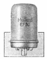
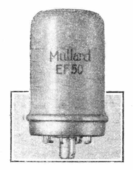
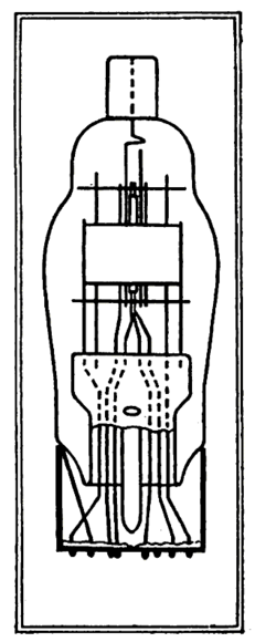
Some of the difficulties encountered in the original method of construction is developed from incandescent-lamp manufacture, can be summarised as follows: (1) In certain valves of the old construction it was found necessary to connect anode and control grid to the opposite ends of the valve, which sometimes complicates receiver design. (2) Long internal connections from the electrodes to the external contacts considerably increase the actual capacities and inductances of the electrodes. This gives rise to serious difficulties when dealing with short waves. (3) Long connecting leads from the electrodes to the contacts also cause appreciable Variation in the effective inter-electrode capacities. This effect is made worse by the presence of the "getter" deposit in the neighborhood of the pinch. (4) The Bakelite used in the manufacture of the base of the valve is rather unsatisfactory, partly because its dielectric constant varies with temperature, and this causes some change in the effective valve capacities during the warming-up period after switching on. In an attempt to solve these problems the Mullard "All-glass" valves have been introduced, and in most respects they prove to be a satisfactory solution, readily adaptable to mass production. The photograph shows the external appearance of one of these valves, the EF50, and Fig. 1 shows the constructional details. The Bakelite base and the foot with its usual pinch have been eliminated and replaced by a machine-made pressed-glass base (A). This glass base includes the chrome-iron leading-out wires. Chrome-iron is chosen for this purpose because it has a coefficient of expansion similar to that of certain qualities of glass, and in other respects it proves to be very suitable for making vacuum-tight seals.
The provision of a locating spigot (H) facilitates the correct insertion of the valve into the socket. This is similar to the method employed in the octal base. The External Contacts
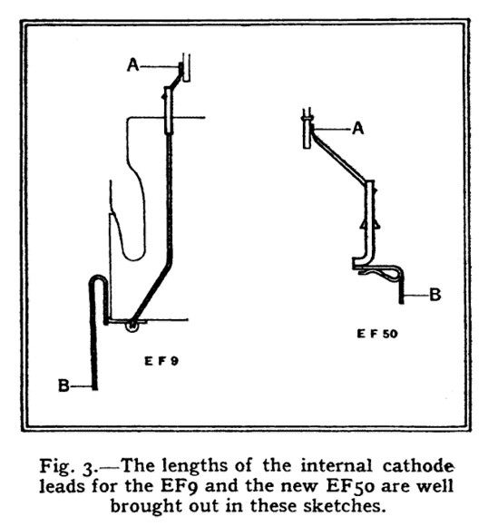
When inserted in the specially designed socket the silver-plated chrome-iron contacts at the base of the valve have a contact resistance of 5 to 8 milliohms, which compares favorably with other existing bases. This method of making the connections has the advantages that there are no soldered joints on the valve, and there is no base which can become loose. More important, the connections between each electrode and the point where the external circuit wiring is soldered to the contact springs on the valve holder are very short. Fig. 2.—The greater length of the internal leads is clearly shown in this drawing of an ordinary valve.
The Internal Leads
The arrangement of the leading-out wires in a typical small valve, the EF9, with a pinch construction is shown in Fig. 2. The wires run more or less parallel with each other inside the foot for a length of approximately 35 mm, compared with 15 mm in the all-glass construction.
Further advantages are obtained by the elimination of the Bakelite base, since Bakelite has comparatively high-dielectric losses and a dielectric constant, which varies, to some extent with temperature change. As a result of this and other causes the capacity variations of valves during the warming-up period give rise to considerable frequency drift eliminating the Bakelite base assists appreciably in the improvement of this defect. The effect described is well brought out by the figures of Table 1. These measurements were made at a frequency of 15 Mc/s and an ambient temperature of 25° C.
As shown in Fig. 1, the control grid connection of the EF50 has been taken to the base. In the pinch construction this would not be permissible, because it would give rise to insufficient screening between the control grid and the anode and heater. The external screen (F) and the internal screen ensure very small anode-to-grid and heater-to-grid capacities in the EF50. The anode-grid capacity is less than 0.002 mmfds, and the grid-heater capacity is less than 0.003 mmfds. These values, which include the capacities of the socket, are quite as small as those measured on the EF9 with the control grid lead taken out to the top cap. It has been found in practice that the input and output capacity tolerance at the EF9 cannot be reduced below ± 0.6 mmfds, the input capacity being 5.0 ± 0.6 mmfds, and the Output capacity 7.0 ± 0.6 mmfds. On the other hand, the all-glass type EF5O can be made with input and output capacity tolerances of only ± 0.2 mmfds. In some applications this is an important advantage. It is possible to work to these reduced tolerances because the lead-out wires in the pressed-glass base are always the same distance from each other, and these distances are greater than in the normal pinch construction. Further, the "getter" deposit is at the top of the bulb and no longer influences the capacities between leads, and the mechanical stability of the electrode System is greater in the new construction. An additional advantage of limiting the "getter" deposit to the top of the bulb is the reduced risk of bad insulation between the support wires, thus obviating the necessity for the well-known white insulation material on the pinch, which can give rise to crackling noises.
In the conventional pinch construction all lead-out and supporting wires in the pinch are in one plane. This necessitates the well-known dome mica construction. In the all-glass valves the supporting wires are arranged in a circle (see Fig. 4). This increases the mechanical stability of the system to such an extent that the additional support of the dome mica construction is not required. The dimensions are of the same order as those of other types of small valves as shown in Table 2.
A point of special importance to set-makers 's the possibility of transporting sets with the valves in position without risk of the valves shaking out. With this object in view the socket for the all-glass valve has been designed on the bayonet-lock principle. This has the advantage that the valve can be firmly secured in its socket by applying comparatively light pressure, followed by a twist, after which the valve cannot be removed unless a twist is applied in the opposite direction. This socket has proved entirely satisfactory for use in apparatus designed for aircraft. Thanks to Jeremy Harmer for contributing this article to radiomuseum.org |
||||||||||||||||||||||||||||||||||||||||


|
Hits: 4040 Replies: 10
Original EF50?
|
|
|
John Turrill
12.Mar.06 |
1
Dear members, I wonder if anyone has more information on what I believe was the original version of the EF50 vhf pentode, which I'm told had a metallised coating (not the aluminium can of later versions) and L-shaped pins, so that the valve had to be pushed in and twisted to lock? (1939?) I'm told there were problems with side pressure on the pins cracking the glass, but I wonder how many were produced? A good photograph or information on the whereabouts of one would be most welcome! Regards from John. |
|
Jacob Roschy
13.Mar.06 |
2
Hello John,
Jacob |
|
Jeremy Harmer
13.Mar.06 |
3
This is familiar but I cannot find anything about it. I wonder if I saw a drawing or was told - though I would generally keep such information. I am sure I have seen more than the short reference in Stokes. |
|
Jeremy Harmer
14.Mar.06 |
4 I have the ref via Rod Burman in the UK: Wireless World Feb 16 1939, page 155 to 156. We have this in our works library and it has a drawing of an all glass valve with the hooked pins. I can send you a scan if you like. |
|
John Turrill
14.Mar.06 |
5
Thank you for the replies from Jacob and Jeremy; like you, Jeremy, I either have or have seen the drawing you refer to - (a bit crude if I remember right; but where? - I didn't see it in W.W.), and I'm thinking it may have been in "Radio Bygones", "Short Wave Magazine" or similar. (probably copied from W.W.?) What I'd really like to see is a good photo of valve and base,- but then, I always was an optimist!!! If the article in W.W. has a fair bit of informative text, then I would be grateful for a scan, but only as and when you can find the time; and if I learn any more I'll keep you posted. It seems the valve would have been developed by Philips, but a lot of Philips archiveal material seems hard to find, at least to me; maybe I ought to try and learn Dutch? Thanks and regards, John. P.S. - I note that Jacob has now requested a scan for the archives, so that would be o.k. for me to examine when you do, thanks, J.T. |
|
Jacob Roschy
14.Mar.06 |
6
Hello Jeremy, I am interested too to have a scan about this document. We can put it to the EF50 page here in our tubes / valves section as additional information. Jacob |
|
Jeremy Harmer
14.Mar.06 |
7
John - I bet it is in Radiobygones - that's the one place I have not looked. I can confirm the WW article has a pic of the valve, though the scan came out a bit speckled, and a line drawing of the valve and base details showing the hooked pins. There is a fair amount of text including, at the end, the bit about inserting the valve and giving it a twist. However the article is about the 'new' valve and thus does not indicate any of the issues that were later found. I wonder if there is a later WW article saying why the EF50 was changed to what it is today. I have put the PDF here for now (2.1Mb): http://www1.leeds.ac.uk/~jeremy/all-glass-valves.pdf Jeremy |
|
Jacob Roschy
15.Mar.06 |
8
Jeremy, Thanks for the document - is it possible send it to me as PNG or GIF file, since I can't processing PDF files ? |
|
John Turrill
16.Mar.06 |
9
Jeremy, many thanks for finding the information regarding the first version of the B9G valve type construction, especially the picture of the first EF50, first sighting I've had! I hope you manage to let Jacob have the file in a format he can utilise; I don't think you can put pdf. files in Irfanview - I tried, but all I could do was print from Adobe, then scan again and put that in Irfanview - my results, at least, weren't good! I'm wondering now if any of the other B9G valves took the same form, with hooked pins?! Regards, John. |
|
Jacob Roschy
16.Mar.06 |
10
Hello Jeremy, it's no longer necessary to send me a converted file - our friend Otmar Jung did this job in the mean time.
|
|
John Turrill
17.Apr.06 |
11
Dear Jacob, http://www.xs4all.nl/~aobauer/
Attachments
|
End of forum contributions about this tube
| Data Compliance | More Information |