
0Z4

|
|
|||||||||||||||||||||||||||||||||||||||||||


|
Hits: 5199 Replies: 8
0Z4 (0Z4)substitute
|
|
|
Omer Suleimanagich
08.Apr.07 |
1
How would one go about making a solid state substitute for this rectifier tube, so that it could function with a vibrator in a car radio? My understanding is, just placing diodes won't work with a vibrator. |
|
Konrad Birkner † 12.08.2014
09.Apr.07 |
2
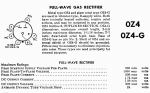
I dont agree with Your pessimism: I think that diodes would in fact do the job. They are rather unlimited compared with the restriction of a gas discharge rectifier. A gas rectifier needs a starter supply voltage, here it is specified with 300 volts per plate. Furthermore a minimum current is necessary to maintain the "arc". Here 30 ma DC output current is the specified minimum. Diodes are free of all such limitations. Only max. current and peak inverse voltage have to be considered, thats all. Maybe a few hundred ohms in series to protect the vibrator contacts are advisable. 1N4007 or similar should be sufficient. Good luck, |
|
Jeffrey Angus
10.Apr.07 |
3
Based on the the following two pages of tube data. http://www.wps.com/archives/tube-datasheets/Datasheets/Raytheon-SP-7649-360-20M/4.JPG and http://www.wps.com/archives/tube-datasheets/Datasheets/Raytheon-SP-7649-360-20M/5.JPG The 0Z4 drops about 24 volts at 110 mA. That means the tube has an effective series resistance of about 218 Ohms or so. This series resistance protects the vibrator (and the diodes) from excessive current as the polarity of the primary is switched back and forth. Excessive current in the transformer secondary, either due to the diodes staying on* (See below), or charging current in the filter capacitor, will cause excess current to flow in the vibrator contacts, or switching transistors. The problem with solid state rectifiers, and again, depending on which ones you use, is the reverse recovery time. 1N4000 series diodes were designed for 60 Hz sine wave rectification. They turn on slow and turn off slow. Minority carriers are what causes a diode to appear "still on" when the polarity reverses suddenly. In the case of a 1N4004 diode, this is greater than 2 uS. If the "still on" time of the rectifiers is longer than the transition time of the wave form, both diodes appear to be "on" at the same time. (Think shorted diode in a bridge rectifier.) Mechanical vibrators have a small "both sides off" time as the armature transition from one contact to the other. Approximately 30 uS or so. Not all solid state vibrators have that feature. (Known as a guaranteed dead time.) However, if the diode's "still on" time exceeds that "both sides off" time of either the solid state or mechanical vibrator, you will end up putting a temporary short across the transformer. This in turn beats the hell out of the vibrator contacts or the switching transistors in the mechanical vibrator. Additionally, repeated stressing of the diodes like this will ultimately result in premature (and or sudden) failure of one or both diodes. Putting some value of resistance in series with the diodes, and this means TWO resistors, one in series with each diode, limits the current that can flow with slower diodes. It also limits the charging current to the first filter capacitor. |
|
Omer Suleimanagich
10.Apr.07 |
4 Should a 0,001 mfd ceramic snubbing cap be placed in parallel to each diode? |
|
Konrad Birkner † 12.08.2014
10.Apr.07 |
5
I appreciate and honor the theoretical considerations. But I think that the max.30µs of a diode (per specification) are short enough to limit the dangerous energy transfer during the transient phase to a bearable amount. And there is a choice of alternatives in the diodes sector. Only the 1N400x series are amongst the cheapest. In the post war time numerous mechanical vibrators worked in combination with selenium rectifiers, which are not really fast switching devices. And theoretically synchronous (self rectifying) vibrators should have never been used at all. There are phase shift problems between Xformer primary and secondary, which to a certain amount apply to our substitution as well. The a.m. series resistors to the diodes are a must of course. |
|
Georg Beckmann
10.Apr.07 |
6
Hi, what you ment as a snubbing cap, if seen parallel to a diode or bridge in a radio device has an other purpose. It is to short the HF to ground, otherwise you modulate your HF signals with the mains ferquency, because the device is periodically less or more connected to ground. Especially on transmitters power supply, but also on receivers. Georg Beckmann |
|
Konrad Birkner † 12.08.2014
10.Apr.07 |
7
Dear Omer, If You would feel safer, spend a few cent more and buy power Schottky or Avalanche diodes. They are fast switching. Dont worry about the poor little vibrator contacts. They have anyway to deal with changing reactive load conditions, where current and voltage are not in phase. That means certain arcing is practically unavoidable. By the way: To my understanding the 1N400x series diodes are neither designed for nor limited to 60 Hz sine wave rectification. They are found in multiple applications e.g. in TV sets. Of course not in high frequency circuits. Anyway: Good luck!
|
|
Rolf Nickel
11.Apr.07 |
8
Dear all, as a non-expert regarding that area I would appreciate very much the provision of one or two simple wiring diagrams in order to improve the general understanding of your discussion. This would also help our beginners to perform follow up. Best regards Rolf |
|
Jeffrey Angus
12.Apr.07 |
9
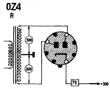
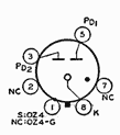
(3)---/\/\/\/----|>|---(8)---|<|----\/\/\/\---(5) (1)---[shell] Parts referenced to http://www.mouser.com Resistor, 2 each, 3 watt 220 Ohm PN: 594-AC03W220R0J data sheet: http://www.vishay.com/docs/28730/acseries.pdf Diode, 2 each, IKV 1 Amp high speed. UF4007 PN: 512-UF4007 data sheet: http://www.fairchildsemi.com/ds/UF/UF4007.pdf Pins (3) and (5) are the anode connections. Pin (8) is the common cathode connection. Pin (1) should go to the metal shell on the 0Z4 and 0Z4A versions. At 110 mA, a 24 V drop is 2.64 watts. Assuming a 50% duty cycle, this gives better than 100% margin on the resistor power ratings. Jeff |
|
Hits: 2729 Replies: 4
0Z4 (Null Z4) ist lt. Brans eine Triode
|
|
|
Arpad Roth † 27.3.17
11.Oct.05 |
1
Verwirrung mit 0 (Null) und o (Oh): Die Röhre 0Z4 (Null Z4) ist lt. Brans eine Triode. Die Röhre OZ4 (OhZ4) ist eine Zweiweg-Gleichrichterröhre. MfG. Arpad Mein Gott, diese Tipfehler bringen mich noch mal um ;-) (Gleichtrichterröhre) |
|
Jacob Roschy
11.Oct.05 |
2
Hallo Arpad, die 0Z4 (mit Null) ist eindeutig eine "ionengeheizte" Zweiweggleichrichterröhre, ich habe selbst einige Exemplare davon, Irrtum ist ausgeschlossen. Die Röhre ist relativ bekannt und steht auch richtig in vielen Datenbüchern, aber die Brans- Bücher wimmeln je nach Ausgabe nur so mit Fehlern ! Ich kann mir schwer vorstellen, dass es irgendwo auf der Welt noch eine Triode mit genau der gleichen Bezeichnung gegeben haben soll ! MfG JR |
|
Arpad Roth † 27.3.17
11.Oct.05 |
3
Hallo Jacob, Zeit bringt Rat und so habe auch ich mich schlauer gemacht. Die 0 (Null) bedeutet ja Null Volt (keine) Heizung, da gasgefüllt auch somit klar. Auf den Schaltplänen kann man eindeutig ein OhZ4 lesen, jedoch die Sockelschaltung bringt Klarkeit. Bekomme heute abend über die 0Z4 und OZ4 von "Brans" die Datenblätter. Wem es interessiert schicke ich diese Gerne zu. Doch gut das es für alle Bereiche hier im RM.org Spezialisten gibt. MfG. Arpad |
|
Hans M. Knoll
11.Oct.05 |
4
Hallo Arpad, kleine Wegzehrung bis heut' Abend. Gruss, Hans Attachments
|
|
Arpad Roth † 27.3.17
11.Oct.05 |
5
Hallo Hans, Du zeigst hier eine "null zet vier" Bin nun gespannt was beim Brans wirklich drinnen steht. Ich besitze dieses Buch nicht und hoffe daher das ich nicht aufs Glatteis geführt wurde. Im Brans sind angeblich beide Röhren gelsitet "null Z4 und oh Z4" MfG. Arpad Wurde leider aufs Glatteis geführt "null zet 4" gibt es nicht. Danke für die Klarstellung. |
End of forum contributions about this tube
| Data Compliance | More Information |